
Drag data were also calculated using PIV velocity fields. Load cell data for lift and drag were obtained for angles of attack from approximately -5 degrees to 5 degrees. These airfoils are characterized by a sharp leading edge and experiments have proven that they can achieve better aerodynamic characteristics at very high angles of attack than certain classical. Prior work has focused on incorporating panel-based aerodynamic solvers with a blade design framework to allow for airfoil shape control within the design loop in a tractable manner. NREL is a national laboratory of the U.S. They make them available on this website. It includes coordinates and a graphic for each airfoil.

Testing was conducted in the 12 inch-diameter water tunnel at ARL Penn State on four shapes – DBLN 526, 4:1 Ellipse, 3.25:1 Rectangle, and a new Optimized Cambered Shape (OCS) designed at UT Knoxville. More efficient blade designs can be found by controlling the airfoil cross-sectional shapes simultaneously with the bulk blade twist and chord distributions. Champaign has put together an excellent database of airfoil shapes. The purpose of this testing is to create a database of lift and drag at various angles of attack to aid in hub design and hub drag prediction.

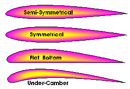
Currently, there is limited experimental data available to predict the drag force on new hub configuratio ns. Results are plotted and tabulated for use in future hub drag prediction toolsets.ĪB - In order to extend the boundaries of helicopter performance and increase forward-flight speed, it is necessary to reduce the drag on the rotor hub, which can account for as much as 30% of the total parasite drag on the helicopter. Continuous variation of the aircraft wing shape to improve aerodynamic performance over a wide range of flight conditions is one of the objectives of. Its probably not the best airfoil choice for a high performance thermal sailplane. A symmetrical airfoil would be fine for an acrobatic glider designed for slope soaring. Then other factors begin to come into consideration. Drag data were also calculated using PIV velocity fields. Its the purpose of the model - its mission - that begins the process. Load cell data for lift and drag were obtained for angles of attack from approximately -5 degrees to 5 degrees. Testing was conducted in the 12 inch-diameter water tunnel at ARL Penn State on four shapes – DBLN 526, 4:1 Ellipse, 3.25:1 Rectangle, and a new Optimized Cambered Shape (OCS) designed at UT Knoxville. N2 - In order to extend the boundaries of helicopter performance and increase forward-flight speed, it is necessary to reduce the drag on the rotor hub, which can account for as much as 30% of the total parasite drag on the helicopter. T1 - Scaled model testing of rotor hub root-end airfoil shapes


 0 kommentar(er)
